Vacuum Casting Design Guide
Vacuum casting imposes design constraints that differ from injection molding and 3D printing, owing to the behavior of flexible silicone tooling. This guide covers design rules specific to the vacuum casting process. For shared specifications — dimensional tolerances, minimum wall thickness, hole diameters, and clearance fits — refer to the 3D Modeling Requirements and What is Vacuum Casting documents.
Draft Angle
Draft angle is the taper applied to vertical walls to facilitate clean part release from the silicone mold during demolding. For parts intended for future transition to injection molding production, incorporating draft from the initial design stage is strongly recommended
| Condition | Recommended Draft Angle |
|---|---|
General recommendation | 1–2° minimum |
Complex geometry / flexible or soft materials | 2° or greater |
Simple geometry / rigid materials | Sub-1° may be acceptable |
Embossed / engraved surface details | Draft recommended |
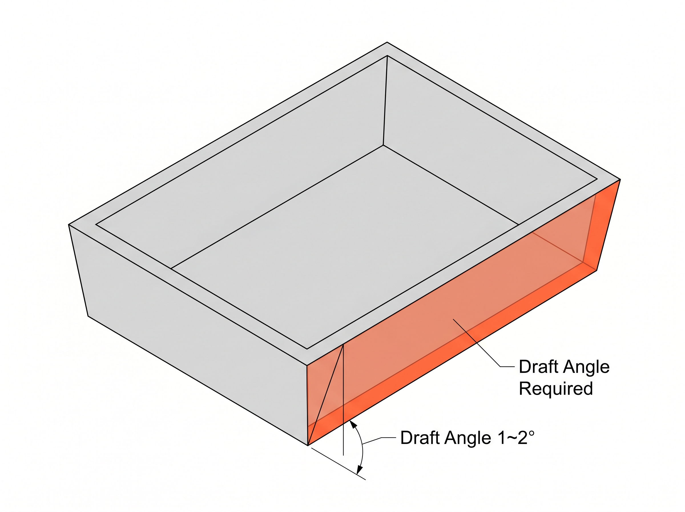
※ Insufficient draft can cause part deformation or mold damage during demolding.
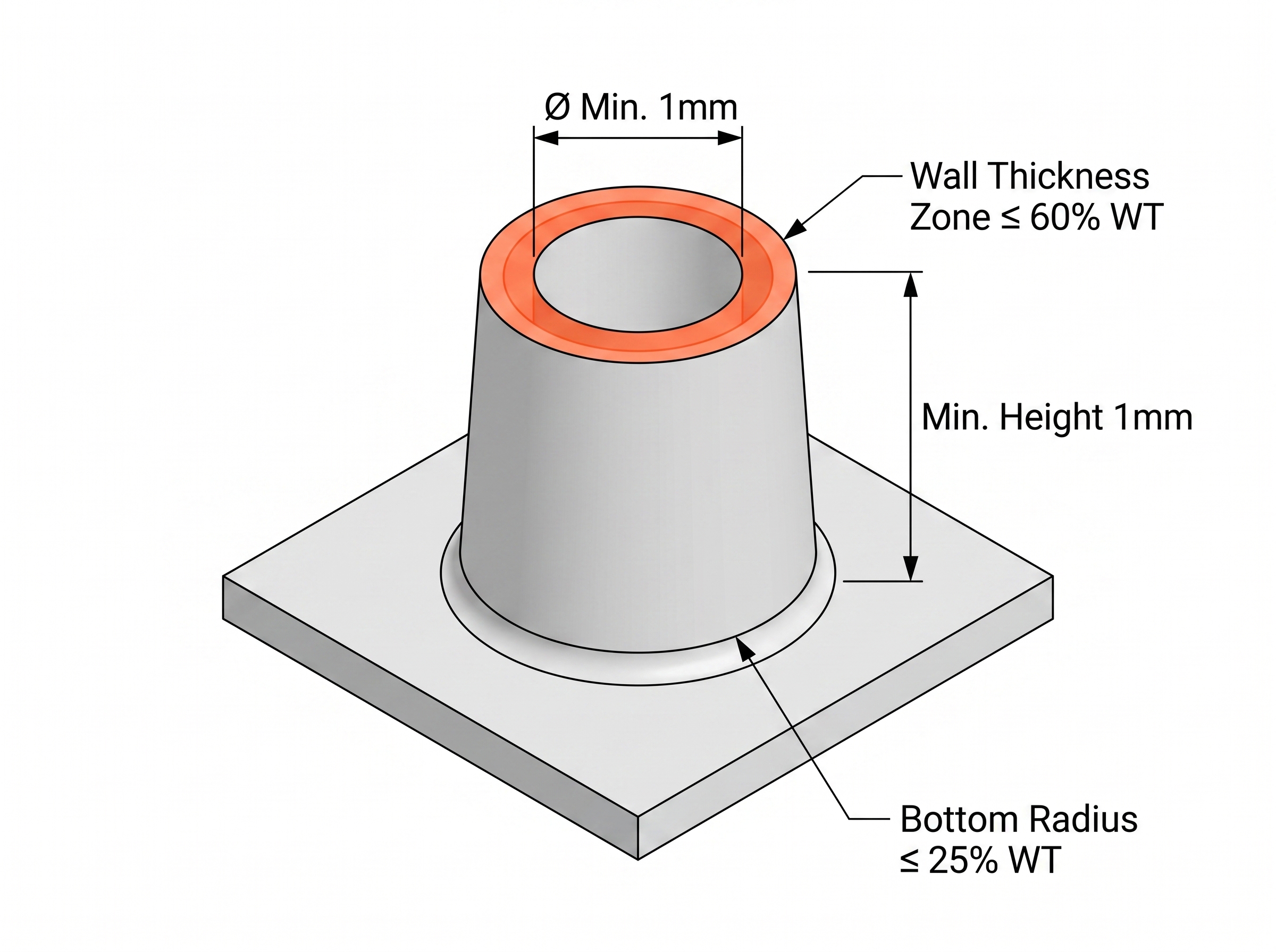
Bosses
Bosses — used for screw bosses, standoffs, and locating features — are prone to sink marks and shrinkage when wall thickness ratios are not maintained.
| Parameter | Specification |
|---|---|
Minimum height | 1.0 mm |
Minimum diameter | 1.0 mm |
Boss wall thickness | ≤ 60% of nominal wall thickness (min. 1.0 mm) |
Base fillet radius | ≤ 25% of nominal wall thickness |
Ribs
Ribs reinforce large flat surfaces and prevent warpage. Maintaining correct thickness-to-height ratios is critical to avoiding sink marks and demolding distortion.
| Parameter | Specification |
|---|---|
Rib thickness | ≤ 60% of nominal wall thickness |
Rib height | ≤ 3× rib thickness |
Root radius | Recommended — reduces stress concentration at rib base |
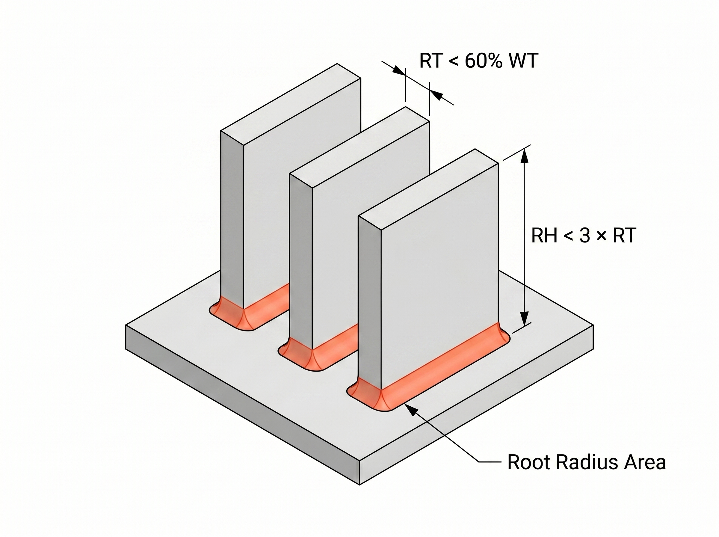
※ Oversized ribs cause sink marks on the opposing surface; excessively tall ribs risk distortion during demolding.
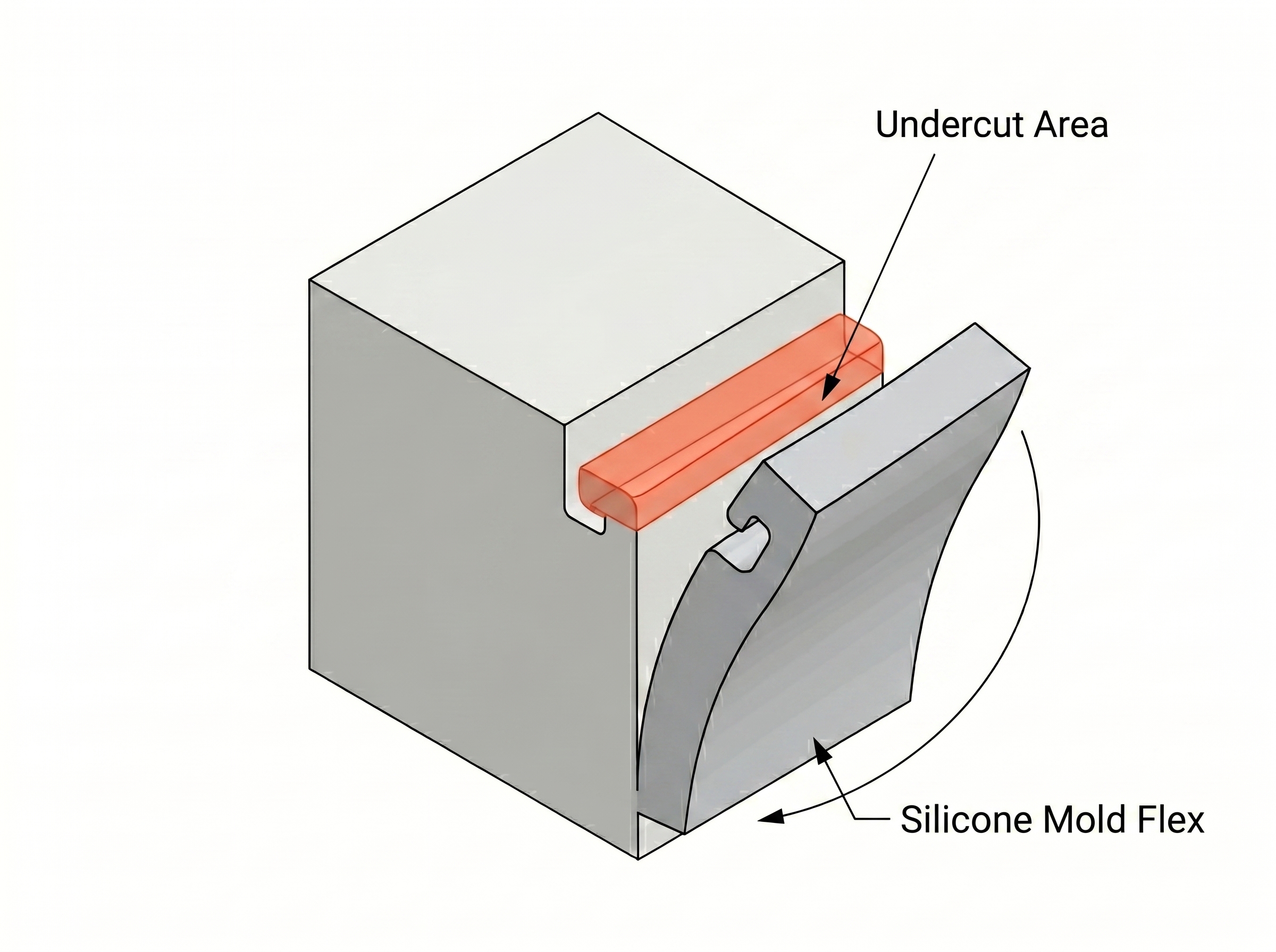
Undercuts
The flexibility of silicone tooling allows undercuts to be released without side-actions or lifters — a key advantage over rigid injection mold tooling.
- Parts targeted for future injection molding production should be designed to injection molding DFM standards from the outset, including appropriate side-action geometry.
- Severe undercuts increase silicone mold cut complexity and reduce tool life. For complex geometries, early alignment on parting direction and mold cut strategy is recommended.
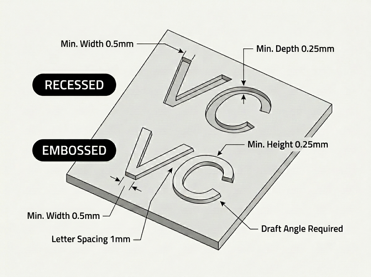
Embossed & Engraved Details
Surface details — text, logos, and patterns — are transferred directly from the master model through the silicone tool to every cast part. Maintain the following minimums to ensure feature fidelity across the production run.
| Parameter | Min. Value |
|---|---|
Feature height (embossed) / depth (engraved) | 0.25 mm |
Feature width (stroke width) | 0.5 mm |
Letter spacing | 1.0 mm |
Draft angle on feature sidewalls | Required for clean release |
Complex undercut geometry in details | Avoid where possible |
Design Requirements Summary
Key design parameters for vacuum casting at a glance. For tolerance and wall thickness values, refer to the 3D Design Guide.
| Parameter | Recommended Value |
Draft angle | 1–2° minimum |
Boss / rib wall thickness | ≤ 60% of nominal wall thickness |
Embossed / engraved feature min. height & width | 1.0 mm |
Maximum part size | 1,200 mm |
Average silicone tool life | 10–20 shots |
※ Specifications in this guide represent general industry practice for vacuum casting with polyurethane resins in silicone tooling. Actual values may vary depending on part geometry, material selection, and surface finish requirements. For project-specific DFM review, contact your Creallo project manager.