Optimizing Sheet Metal Design: Key Standards for Bend Radius, Hole Placement, and Flat Patterns
To prevent manufacturing defects and minimize production costs when designing sheet metal parts, it is crucial to consider these core design parameters (bend radius, hole/slot offsets, and flat pattern standards).
Go to Creallo Sheet Metal Fabrication Service for an Instant Quote >>
Tolerance Optimization Guide
Due to the nature of the process, sheet metal fabrication has wider dimensional variances compared to CNC machining. It is most cost-effective to specify tight tolerances only where precision is functionally essential. Unnecessarily strict tolerances increase manufacturing difficulty, leading to higher costs and longer lead times.
Standard Manufacturing Tolerances
The following are the reliably achievable tolerance standards in sheet metal fabrication:
| Item | Tolerance Standard |
|---|---|
| Laser Cutting — Length Tolerance | ±0.2 ~ ±0.5mm |
| Laser Cutting — Hole Diameter | ±0.08 ~ ±0.12mm |
| Bending Angle | ±0.5° ~ ±1.0° |
Design Tip
When designing based on Outer Dimensions (OD), the final edge measurement may vary due to angular tolerances. Always account for cumulative tolerances and provide sufficient clearance. For parts requiring high-precision assembly, consider secondary CNC machining (post-processing) after sheet metal fabrication.
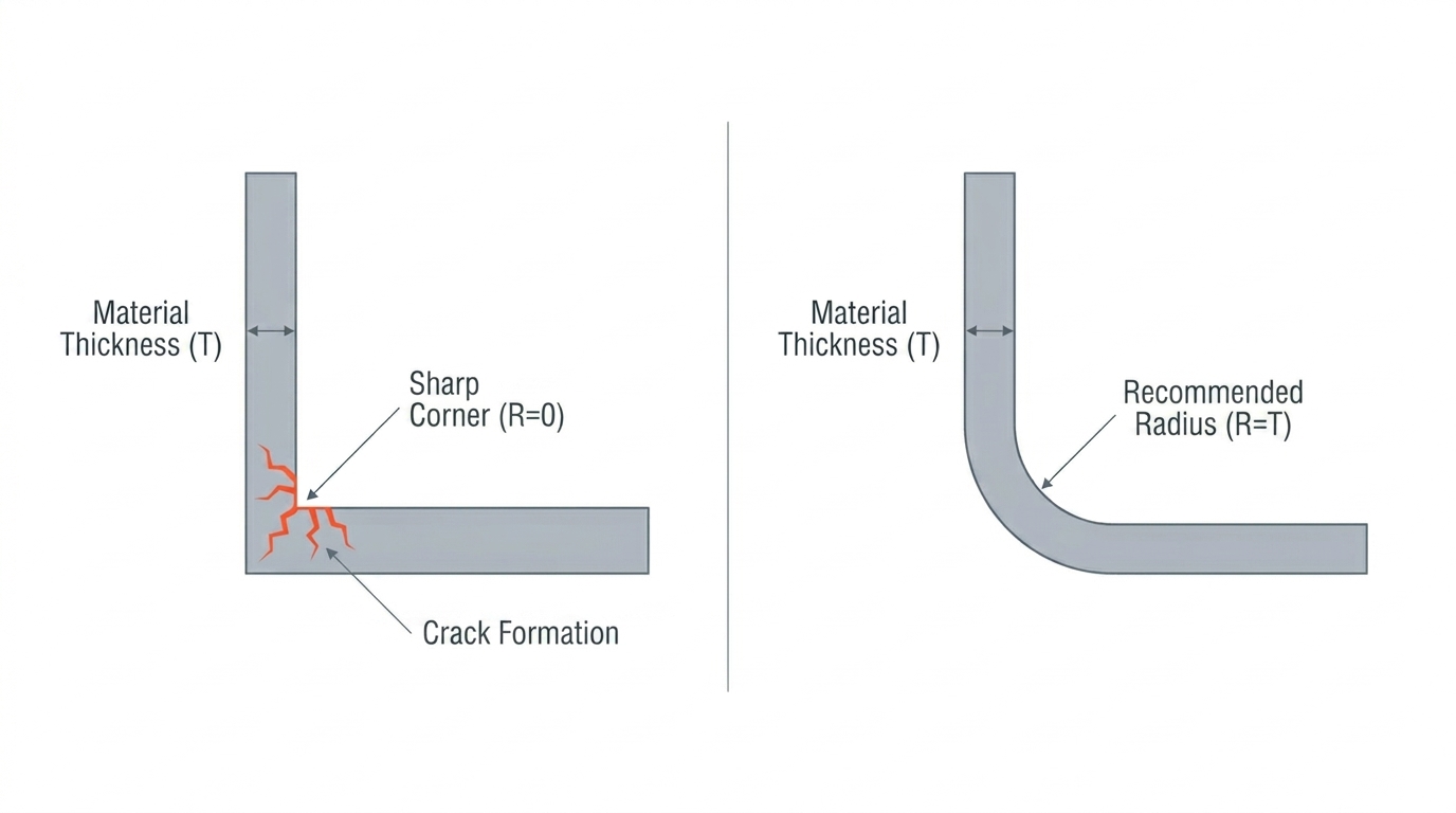
Inside Bend Radius & Crack Prevention
If the Inside Bend Radius (R) is smaller than the material thickness, micro-cracks or material failure can occur at the bend.
| Material | Plate Thickness | Recommended Min. Inside Radius (R) |
|---|---|---|
| Steel (SPCC) | 3mm or less | 1T |
| Steel (SPCC) | Over 3mm | 1.5T |
| Stainless Steel (SUS304/316L) | All thickness | 1.5T |
| Aluminum (AL5052/6061) | All thickness | 1T |
(T = Plaste Thickness)
- Cost-Saving Tip: Whenever possible, apply the same bend radius to all flanges within a single part. This reduces the number of tool changes, effectively lowering the total manufacturing cost.
- Edge Treatment: Sharp internal corners are points of stress concentration. It is recommended to apply a Fillet of at least R 0.5 to both internal and external corners.
Design for Holes, Slots, and Bridges
To prevent material deformation during bending and thermal distortion during laser cutting, the following offset standards must be observed.
| Target Item | Minimum Value | Recommended Value |
|---|---|---|
| Hole Edge to Bend Line | 2T | 3T + R |
| Slot Edge to Bend Line | 3T | 4T + R |
| Min. Distance Between Holes | T | 2T |
| Min. Hole Diameter | T | 1.5T |
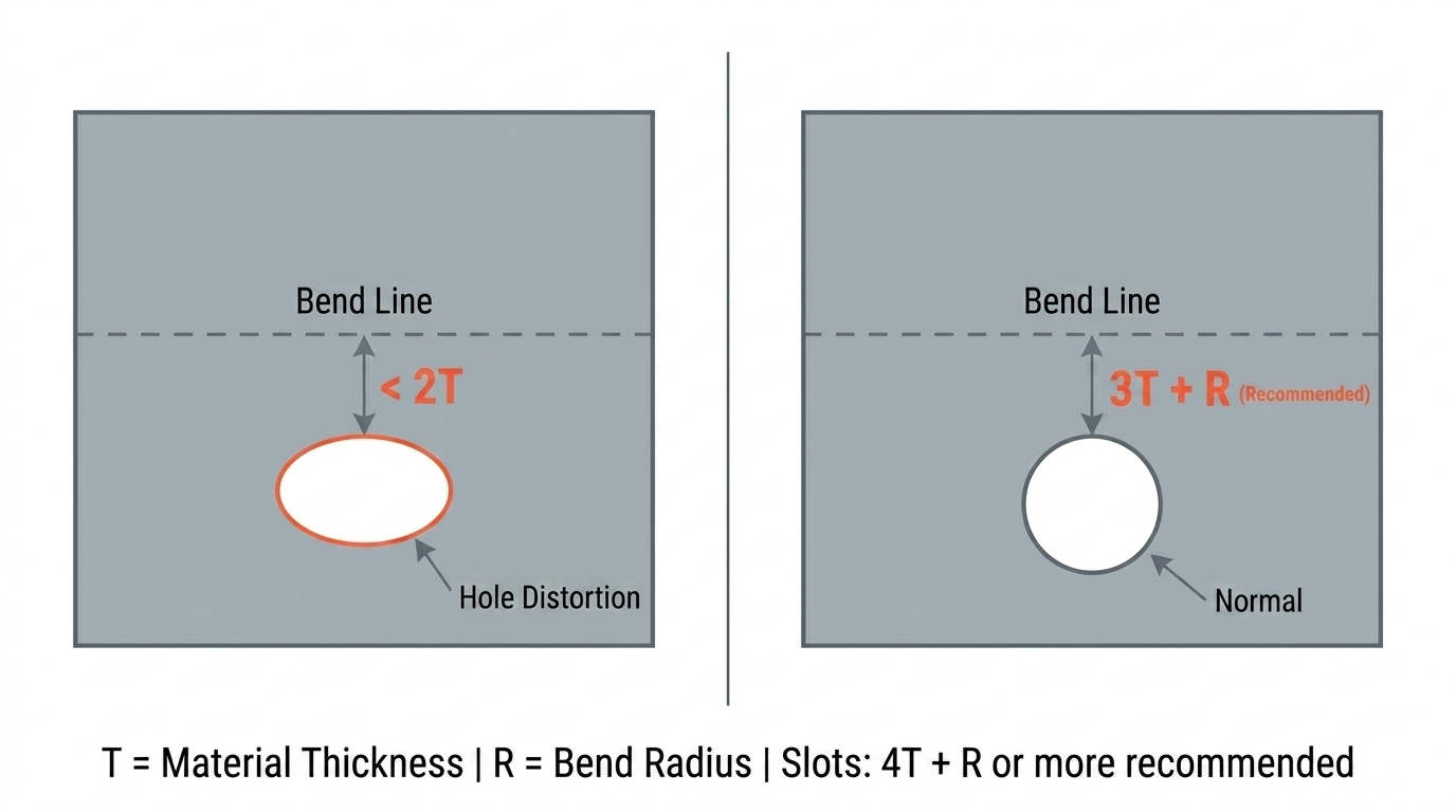
- Hole Deformation: If the offset is less than the minimum, the hole may stretch into an oval shape during the bending process, leading to assembly issues.
- Bridge (Wall Thickness) Design: The bridge (remaining material) between two holes or between a hole and the outer edge must be at least equal to the material thickness (T). If the bridge is too thin, the heat from laser cutting can cause the material to warp or melt.
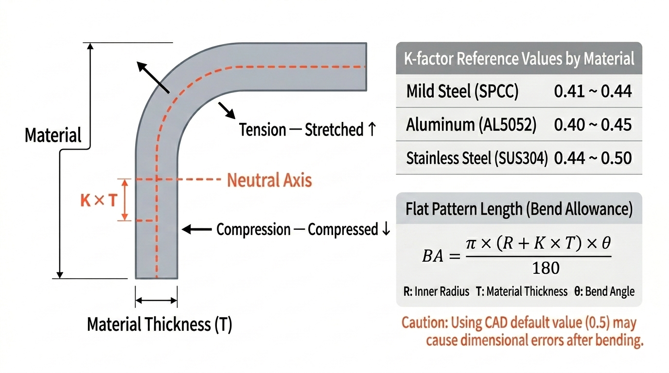
K-Factor for Accurate Flat Patterns
The K-Factor is a constant that determines the position of the Neutral Axis during bending. Setting the correct value based on the material and fabrication method ensures that the final product matches your design dimensions.
| Material | Recommended K-Factor Range |
|---|---|
| Mild Steel (SPCC) | 0.41 ~ 0.44 |
| Aluminum (AL5052/6061) | 0.40 ~ 0.45 |
| Stainless Steel (SUS304/316L) | 0.44 ~ 0.50 |
Addressing Side Bulge & Bend Relief
When a flange is bent, the material at the root of the bend is squeezed outward, creating a "Side Bulge." If this area needs to sit flush against another surface, you must include a Bend Relief cut to prevent interference. Check your 3D CAD software’s automatic compensation settings to reflect this in your design.
Final Sheet Metal Design Checklist
Before finalizing your drawing, verify these 9 points to maximize manufacturing efficiency.
- Does the Inside Bend Radius (R) meet the minimum material standards?
- Are the bend radii uniform for all flanges within the part?
- Are all hole diameters at least equal to the material thickness (T)?
- Are holes offset from the bend line by at least 2T?
- Are slots offset from the bend line by at least 3T?
- Is the bridge thickness at least equal to the material thickness (T)?
- Is the K-Factor set correctly for the chosen material?
- Is the Flange Length at least 4 times the material thickness?
- Have fillets (R) been applied to sharp internal corners?
Need professional sheet metal fabrication?
Creallo offers a one-stop solution from laser cutting to NCT, bending, welding, and post-finishing (anodizing, powder coating, etc.). With our ISO 9001 certified quality management, we support everything from prototyping to mass production.