Common Injection Molding Defects: Causes and Solutions
When producing a new part through injection molding and moving into mass production, unexpected quality issues can show up due to variables like injection conditions, temperature, and material properties. This guide walks through the most common injection molding defects, why they happen, and how to fix them.
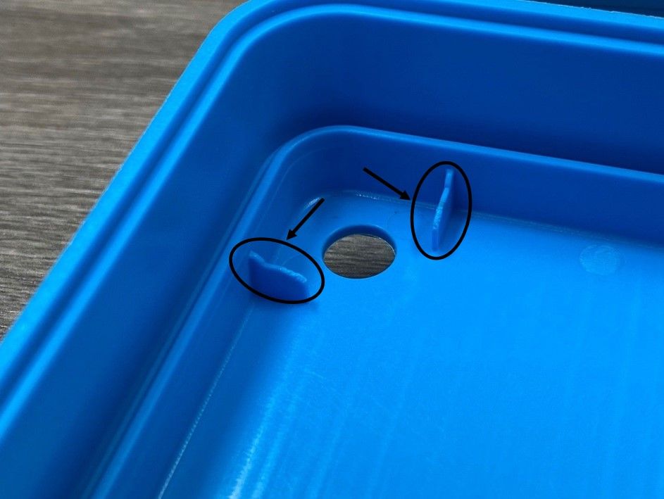
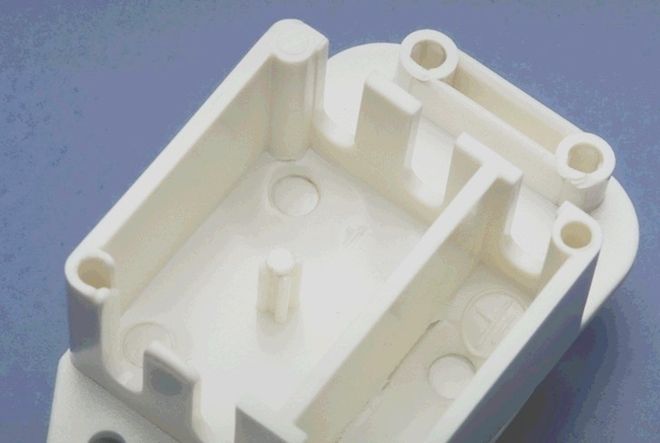
A short shot occurs when the molten resin fails to completely fill the part geometry, most often at ribs, bosses, or thin edges.
Short shot defect example
Causes and Solutions
Process Conditions
Cause
Injection pressure is too low.
Solution
Increase injection pressure.
Cause
Resin flowability is insufficient.
Solution
Raise the mold temperature,
Raise the resin temperature, and/or increase injection speed (especially effective for thin-walled sections).
Cause
Injection speed is too fast, preventing proper gas venting or clogging the vents.
Solution
Moderately reduce injection speed. If using multi-stage speed control, slow down the final stage.
Machine
Cause
Pressure drops as the resin travels from nozzle → sprue → gate → cavity.
Solution
Shorten the nozzle length, shorten the sprue length, and shorten the gate length while increasing its width or thickness (diameter).
Cause
A small nozzle diameter can prevent proper filling due to high pressure loss.
Solution
Increase the nozzle diameter.
Cause
The machine's injection capacity is equal to or smaller than the part's volume (weight).
Solution
Use a machine whose injection capacity is at least 50% greater than the part weight.
Cause
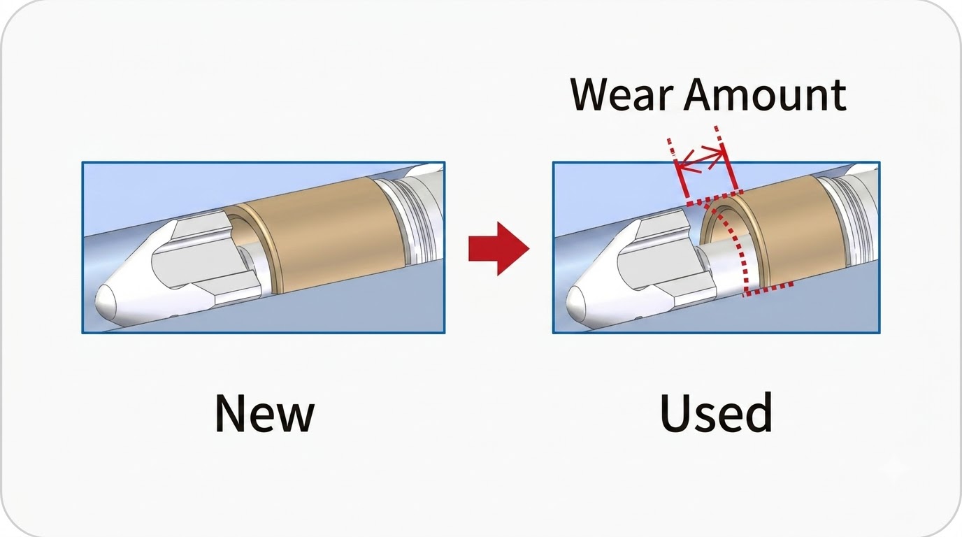
A worn check ring allows resin to flow backward during filling.
Solution
Since the check ring is a consumable part, inspect and replace it regularly.
Mold
Cause
With materials like POM or flame-retardant resins, parts may mold well initially but develop short shots later as contaminants clog the gas vents.
Solution
Clean the gas vents.
Cause
Flame-retardant resins contain UL-certified halogen gas additives that can clog vents with residue.
Solution
Maintain vent function through regular cleaning, maintenance, and inspection records.
Cause
In multi-cavity molds, poor gate balance causes cavities near the sprue to fill first and distant cavities to fill later, resulting in short shots.
Solution
Use a smaller gate cross-section near the sprue and a larger one farther away so all cavities fill simultaneously.
Cause
Runners, gates, or sprues are too small.
Solution
A wider gate cross-section generally gives the best balance — but if the gate is too wide, gate sealing takes longer, which can cause packing pressure issues and shrinkage defects. If the runner cross-section is too small, the molten resin loses flowability; increasing the runner size is usually more effective than enlarging the gate alone.
Material
Cause
Poor resin flowability.
Solution
Use a higher-flow grade of the same resin type. Flowability can be evaluated using the L/t ratio (PS: L/t = 220–300; PC: L/t = 100–150). Resins with poor L/t values benefit from multiple gates, or from hot-runner systems with sequential valve gates.
Flash / Burr
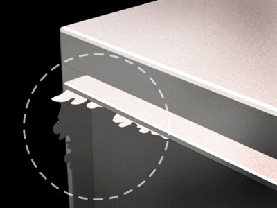
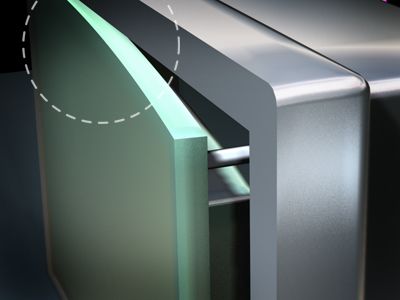
Flash occurs when resin seeps into gaps — between the fixed and moving mold halves, slide sections, insert clearances, or ejector pin gaps — creating an unwanted thin film on the part.
Flash/burr defect example
Causes and Solutions
Process Conditions
Cause
Injection pressure is higher than necessary.
Solution
Lower the injection pressure (secondary/holding pressure)
Lower the resin temperature
Lower the mold temperature,
Reduce the shot size
Lower the final injection speed stage.
Machine
Cause
Insufficient clamping force (clamping force = mold internal pressure × projected area).
Solution
Use a machine with higher clamping tonnage.
Mold
Cause
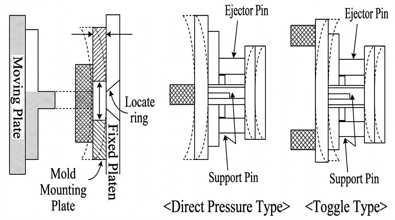
Insufficient mold rigidity — a thin fixed-side mounting plate can bow under pressure.
Support pin position differences between toggle-type and direct-pressure clamping units can cause the moving platen to deflect in opposite directions if the mold is moved between machine types.
Solution
Use a stronger mold material or increase mold plate thickness.
Foreign matter trapped in the mold prevents proper mold closure.
Solution
Remove foreign matter from the mold.
Cause
Worn guide pins
Solution
Replace guide pins, or measure wear and confirm remaining clearance.
Cause
Weak mold material deforms over long-term use, or the mold has degraded from age.
Solution
Upgrade to a wear-resistant mold material.
Cause
Burr occurs repeatedly and consistently.
Solution
The mold needs to be reworked.
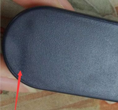
Sink Mark
Sink marks are surface depressions caused by shrinkage, typically occurring near ribs.
Sink mark defect example
Causes and Solutions
Process Conditions
Cause
Injection pressure is too low.
Solution
Increase injection pressure.
Cause
Holding (packing) time is too short.
Solution
Extend the holding time until the gate freezes (i.e., until part weight stops changing).
Cause
Resin temperature is too high, causing excessive shrinkage.
Solution
Lower the resin temperature.
Cause
Mold temperature is too high, causing slow cooling and excessive shrinkage.
Solution
Lower the mold temperature.
Cause
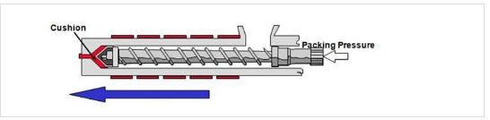
Cushion amount is too large or too small.
Solution
Adjust the cushion amount to an appropriate level (around 10 mm).
Machine
Cause
A small nozzle diameter causes high pressure loss, so pressure isn't transmitted effectively.
Solution
Increase the nozzle diameter.
Mold
Cause
With materials like POM or flame-retardant resins, parts may mold well initially but develop defects later as contaminants clog the gas vents.
Solution
Clean the gas vents.
Cause
Flame-retardant resins contain UL-certified halogen gas additives that can clog vents with residue.
Solution
Maintain vent function through regular cleaning, maintenance, and inspection records.
Cause
In multi-cavity molds, poor gate balance causes cavities near the sprue to fill first and distant cavities to fill later.
Solution
Use a smaller gate cross-section near the sprue and a larger one farther away so all cavities fill simultaneously.
Cause
Runners, gates, or sprues are too small.
Solution
A wider gate cross-section gives the best balance, though an excessively wide gate delays gate sealing and can cause packing/shrinkage issues.
A larger runner cross-section is usually more effective than enlarging the gate alone.
Material
Cause
Low-shrinkage resins produce smaller sink marks.
Solution
Use a lower-shrinkage grade within the same resin family.
Cause
PE, PP, and POM shrink significantly.
Solution
If a material substitution is possible, switch to an amorphous resin such as PC or ABS.
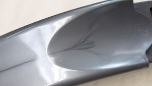
Flow Mark
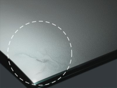
Flow marks are visible streak patterns on the part surface, typically appearing near the gate and at the last-filled areas.
Flow mark defect example
Causes and Solutions
Process Conditions
Cause
Resin temperature is too low, causing a solidified layer to form quickly and reducing flowability.
Solution
Increase the resin temperature.
Cause
Mold temperature is too low, causing the same early solidification effect.
Solution
Increase the mold temperature.
Cause
Injection speed is too slow, causing the same early solidification effect.
Solution
Increase injection speed.
Use multi-stage speed control to precisely manage the flow rate near the gate.
Cause
Pressure doesn't transmit easily to the flow end.
Solution
Increase holding pressure, since slow flow is the underlying cause.
Mold
Cause
Resin that solidifies near the nozzle gets injected into the cavity, forming a cold slug.
Solution
Add a cold slug well for indirect gates.
Cause
With direct gates, particularly for PC, heat loss increases viscosity.
Solution
Avoid "touch molding" and use "untouch molding" instead.
Cause
Poor gas venting increases flow resistance.
Solution
Ensure gas vents function properly.
Cause
In multi-cavity molds, resin cools while traveling through long runners, producing flow marks.
Solution
Improve gas venting.
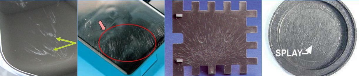
Silver Streak
Silver streaks are silver-colored streaking patterns on the part surface.
Silver streak defect example
Causes and Solutions
Process Conditions
Cause
Insufficient back pressure during plasticization draws in air; this air, surrounded by resin, ruptures inside the cavity and appears on the mold surface (occurs regardless of whether the resin is crystalline or amorphous).
Solution
Increase back pressure (PB) to prevent air intake during plasticization.
(Note: excessive suck-back, even with higher back pressure, can increase silver streaking.)
Cause
Frictional heat during metering or molding thermally decomposes the resin into gas, which ruptures inside the mold.
Solution
Keep screw RPM within an appropriate range.
Mold
Cause
Shear friction inside the mold.
Solution
Avoid overly thin wall sections or overly complex mold geometry.
Cause
Small runner, gate, or sprue cross-sections.
Solution
Maintain vent function through regular cleaning, maintenance, and inspection records.
Cause
Uneven wall thickness within the mold.
Solution
Design the part to avoid abrupt thickness changes.
Cause
Poor gas vent exhaust.
Solution
For flame-retardant resins or large-volume parts that generate more gas, design vents thoroughly, and clean or widen vents when they become clogged or lose effectiveness.
Material
Cause
Insufficient resin drying leaves excess moisture in the material.
Solution
Ensure resin is fully dried in a hopper dryer.
Cause
Mixing of dissimilar resins.
Solution
Take care to avoid cross-contamination between different resin types.
Cloudy Surface (Gas Marks)
Cloudy surface refers to a hazy, foggy discoloration on the part surface.
Cloudy surface defect example
Causes and Solutions
Process Conditions
Cause
Resin fails to properly transfer/replicate against the mold surface.
Solution
Adjust mold temperature.
If gas generation is causing the cloudy surface, lower the mold temperature.
If the surface finish transfer is poor due to low mold temperature, raise it instead.
When cloudy surface occurs, try lowering the mold temperature first, and raise it if that doesn't help (raising temperature generally takes less time than lowering it).
Mold
Cause
Rough mold surface finish.
Solution
Polish the mold surface to improve cloudy surface issues.
Cause
Degraded chrome plating that has partially worn away.
Solution
Fully strip and reapply the chrome plating.
Cause
Lubricant or release agent residue on the mold surface.
Solution
Clean the lubricant and release agent from the mold surface.
Cause
Poor venting.
Solution
Eliminate trapped air and ensure gas vents are functioning properly.
Weld Line / Knuckle Line
Weld lines appear as visible seams where two flow fronts meet, similar to a weld seam in metal.
Causes and Solutions
Process Conditions
Cause
Injection speed is too slow, so the resin loses heat to the mold before the two flow fronts meet.
Solution
Increase injection speed.
Cause
Injection speed is too fast, preventing adequate gas venting; trapped air compresses adiabatically and delays flow, and the resin loses heat to the mold before the flow fronts meet — this often occurs at the end of fill.
Solution
Check venting near the weld line area and adjust injection speed.
Cause
Resin temperature is too low where the two flow fronts meet.
Solution
Increase resin and/or mold temperature.
Cause
Injection pressure is too low to maintain sufficient flow speed.
Solution
Increase injection pressure.
Mold
Cause
Poor venting can cause weld lines to form.
Solution
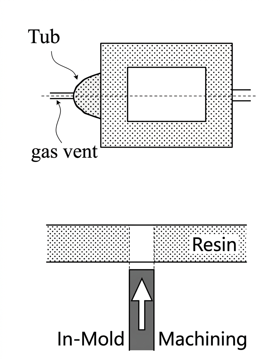
Add a "tub" feature to relocate the weld line into a vented pocket, then remove the tub after molding to eliminate the visible weld.
Cause
Poor venting creates air resistance that impedes and delays resin flow, causing it to cool and form a weld line.
Solution
Modify or clean the mold to improve venting — use parting lines, slide pins, core pins, or porous steel inserts for venting.
Cause
Parts with holes or multiple gates create weld lines where flow fronts meet.
Solution
Adjust gate position and count to relocate the weld line elsewhere. Alternatively, use heating/cooling (heating the weld area to ~200°C with a halogen lamp, then cooling — note this changes mold dimensions and requires durable materials due to repeated thermal cycling), or use in-mold machining (venting via a pin hole under holding pressure after fill) to eliminate the weld line.
Bubble / Void
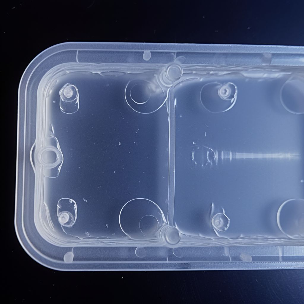
Bubbles or voids are internal or surface gas pockets within the part.
Bubble/void defect example
Causes and Solutions
Process Conditions
Cause
Bubble formation from trapped air.
Solution
Increase back pressure and lower resin temperature.
Cause
Insufficient resin is supplied to compensate for volumetric shrinkage in thick sections, creating voids.
Even with sufficient holding pressure, if resin and mold temperatures are too low, pressure loss along the flow path prevents enough resin from reaching thick sections to compensate for shrinkage.
Solution
Increase resin temperature and mold temperature.
Mold
Cause
Abrupt wall thickness changes prevent even pressure transmission, causing microscopic voids as shrinkage occurs or trapped gas bubbles merge and grow.
Solution
Clean gas vents and design the part to avoid abrupt wall thickness changes.
Cause
Abrupt wall thickness changes cause the surface to solidify quickly while the interior shrinks significantly.
Solution
Design the part to avoid abrupt wall thickness changes.
Cause
Even with sufficient holding pressure, a thin gate location makes pressure transmission difficult, preventing enough resin from compensating for shrinkage.
Solution
Position the gate at a thicker section of the part.
Cause
Small runner and gate cross-sections cause high pressure loss, preventing holding pressure from transmitting effectively.
Solution
Increase runner and gate size.
Material
Cause
Crystalline resins with slow crystallization rates solidify quickly at the surface while the hotter interior solidifies more slowly, creating internal voids.
Solution
Use a resin with a faster crystallization rate.
Black Streak / Brown Striation
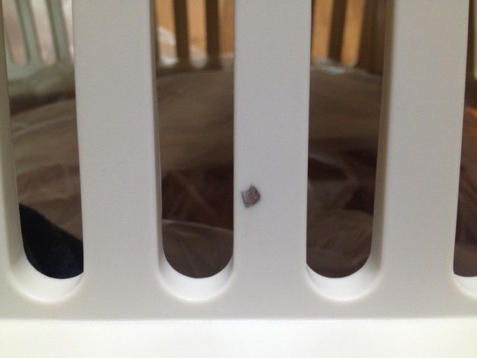
Black or brown discoloration and streaking on the part surface.
Black streak defect example
Causes and Solutions
Process Conditions
Cause
Carbonization from frictional heat at the gate.
Solution
Lower injection speed and injection pressure.
Cause
Using the same resin after a shutdown without purging causes repeated heating/cooling/reheating cycles that carbonize residual resin.
Solution
Keep the barrel warm during downtime. For example, acrylic held at 220°C that cools to room temperature over a break tends to develop black spots; keeping it warm can reduce or eliminate this on the next run. PP (food-grade, additive-free), PE (medical-grade, additive-free), and PMMA also benefit from being kept warm, though it may not eliminate the issue entirely.
Machine
Cause
Resin lingering in gaps near the nozzle inside the cylinder carbonizes and gets carried into the part.
Solution
Clean the internal nozzle gaps frequently.
Cause
Resin trapped for extended periods around the screw's check ring carbonizes and enters the part.
Solution
Clean the check ring area frequently.
Cause
Screw surface damage traps resin in the flow channel, where it stagnates, carbonizes, and enters the part.
Solution
Repair the screw surface, and apply coating if needed to reduce resin adhesion.
Cause
Using a screw with a short compression zone or long metering zone for easy-to-melt resins causes overheating/decomposition that enters the part.
Solution
Replace the screw to avoid overheating in the compression and metering zones during plasticization.
Mold
Cause
Poor venting causes resin to carbonize inside the mold.
Solution
Clean or enlarge gas vents to improve venting.
Cause
Mold lubricant residue on the mold surface carbonizes when contacted by incoming resin.
Solution
Clean the mold frequently.
Material
Cause
Switching from ABS to PC/ABS without proper purging can cause defect rates above 10% due to black spotting (at high temperatures, PC/ABS can carbonize resin residue left in the screw, or resin that underwent high-temperature exposure can stick to the screw and carbonize, shedding debris into subsequent shots).
Solution
When switching between PC/ABS and ABS, thoroughly clean the barrel interior using a high-viscosity PE purge compound.
Crazing / Cracking
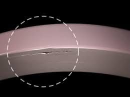
Cracking occurs when differential cooling rates due to wall thickness variation create shear stress at the interface between the solidified and molten layers, exceeding the material's elastic limit and causing internal or external cracks.
Crazing/cracking defect example
Causes and Solutions
Process Conditions
Cause
Excessive injection pressure causes significant shear stress and residual stress.
Solution
Lower injection pressure, lower holding pressure, reduce holding time, increase resin temperature, increase mold temperature, and/or apply annealing to prevent cracking/crazing (anneal at 15–20°C below the heat deflection temperature).
Injection speed is too fast, preventing proper gas venting or clogging the vents.
Solution
Moderately reduce injection speed; if using multi-stage speed control, slow down the final stage.
Mold
Cause
In insert molding, differences in thermal expansion (shrinkage rate) between the metal insert and resin cause cracking.
Solution
Preheat the metal insert to 50–60°C (sometimes up to 100°C) before injection.
Delamination
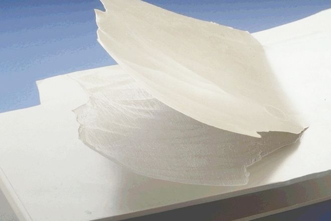
Delamination occurs when the skin layer of the molded part peels away (typically near the gate or in thin sections), leaving a mica-like layered structure that separates when peeled.
Delamination defect example
Causes and Solutions
Process Conditions
Cause
Very low resin or mold temperature causes the resin to solidify immediately upon contacting the mold surface.
Solution
Lower injection pressure, raise resin and mold temperature, adjust back pressure and screw RPM, and dry the resin thoroughly.
Mold
Cause
Too few runners/gates, or a thin and complex part geometry, creates excessive shear stress during filling.
Solution
Enlarge runners and gates, and design the mold with shear stress during filling in mind.
Material
Cause
Mixing incompatible dissimilar resins — often from incomplete purging (mixing inside the cylinder during molding) or contaminated raw material.
Solution
Purge thoroughly, and clean the cylinder interior when necessary.
Jetting
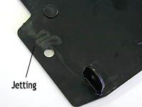
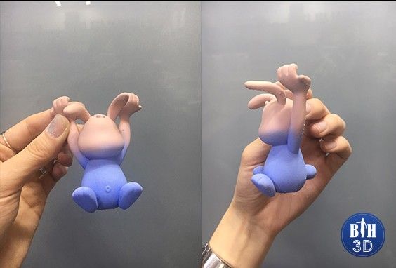
Jetting occurs when molten resin passing through the gate reaches the far end of the part and solidifies into a snake-like pattern.
Jetting defect example
Causes and Solutions
Process Conditions
Cause
Fast resin flow combined with the inertia of injection speed and the elasticity of the molten resin at the gate.
Solution
Reduce injection speed near the gate so resin fills the gate area sufficiently before speeding up again. Once the area around the gate is filled, increasing speed afterward won't cause jetting, since the increased viscosity of the melt and friction between the solidified and molten layers create enough flow resistance to prevent it.
Cause
No feature near the gate to slow down flow velocity.
Solution
Use a side gate to prevent jetting — this allows higher injection speed near the gate without causing the defect. Alternatively, install a core pin in front of the gate.
Warpage
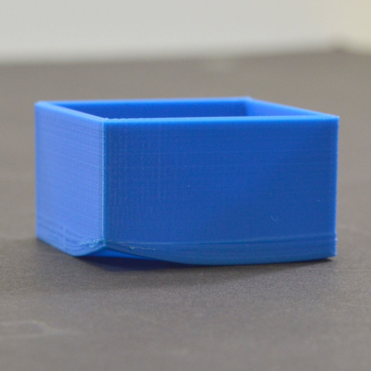
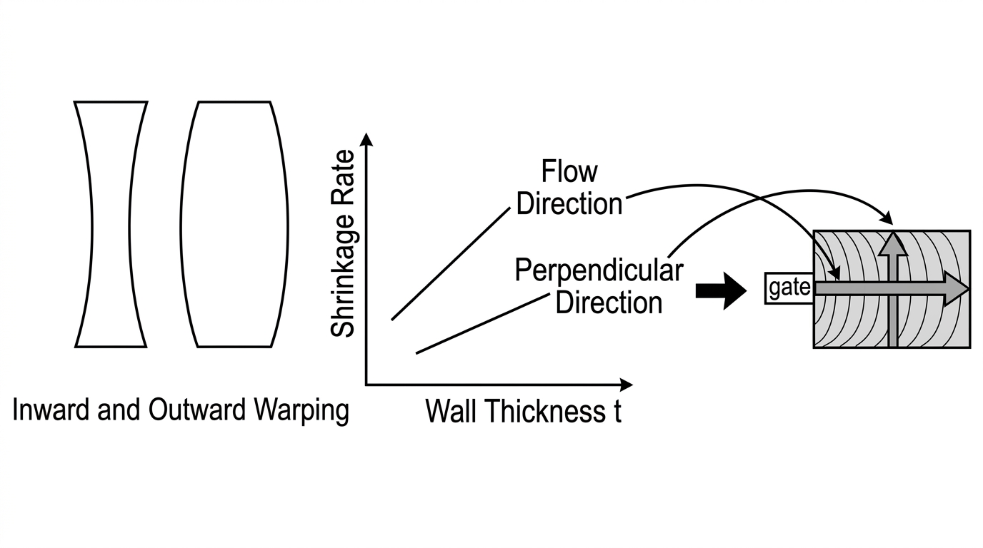
Warpage is shrinkage or distortion in a specific direction across the part.
Warpage defect example
Causes and Solutions
Mold
Cause
Uneven wall thickness causes greater shrinkage in thick sections and less shrinkage in thin sections, leading to warpage from differential shrinkage.
Solution
Design the part to minimize thickness variation.
Cause
Uneven mold cooling causes greater shrinkage where mold temperature is higher and less shrinkage where it's lower. Box-shaped parts, especially in PP, commonly warp inward.
Solution
Rapidly cool the inside of the box and slowly cool the outside to correct inward warping — but note that over-cooling the inside to fix inward warp can introduce outward warp instead.
Material
Cause
Orientation of polymer chains or reinforcing fibers along the flow direction creates differential shrinkage between the flow direction and the cross-flow direction, causing warpage.
Solution
Apply separate shrinkage rates for the flow direction and cross-flow direction during mold design to achieve the desired final dimensions.
Color Inconsistency
Color deviation from the resin's intended color, or inconsistent color across parts.
[Image: Color inconsistency defect example]
Color inconsistency defect example
Causes and Solutions
Process Conditions
Cause
Color variation arises from differences in molding temperature and residence time in the injection cylinder. Even with the same resin, color can vary due to resin temperature, residence time, or differences between machine models; gloss differences can also contribute to perceived color variation.
Solution
Monitor actual resin temperature rather than the set temperature, and keep cylinder residence time consistent. Maintain consistent injection speed, back pressure, and other process conditions to keep resin temperature stable.
Material
Cause
Pigment is not uniformly dispersed in the resin (typically near the gate).
Solution
Use pre-colored (compounded) pellets, and adjust back pressure.
Cause
Insufficient thermal stability of the colorant (appears across the entire surface).
Solution
Evaluate alternative colorants, and account for the resin's thermal stability relative to cylinder residence time.
Cause
Crystalline resins can show color variation due to cooling rate differences.
Solution
Set the mold temperature appropriately for the specific resin.
Surface Gloss Defect (Cloudy)
Uneven surface gloss across the part.
Surface gloss defect example
Causes and Solutions
Process Conditions
Cause
Gloss level varies with molding conditions.
Solution
Higher injection speed (pressure) generally increases gloss; higher mold temperature improves gloss; resin temperature also affects gloss (higher resin temperature generally increases flowability and gloss). Poor resin drying can also degrade gloss.
Mold
Cause
Poor mold surface polishing.
Solution
Improve mold surface polishing (for fully transparent parts, plating the mold surface can further improve gloss).
Cause
Release agent residue or other contamination on the mold surface.
Solution
Clean the mold surface and strictly control release agent use.
Resin
Cause
Insufficient resin flowability (reduces gloss).
Solution
Increase resin temperature.
Cause
Volatile gas content in the resin reduces gloss (thermal decomposition of the resin increases gas generation).
Solution
Dry the resin thoroughly to suppress gas generation, and mold at an appropriate temperature with short cylinder residence time.
Stress Whitening
Localized whitening on part of the product.
Causes and Solutions
Process Conditions
Cause
Overpacking creates high cavity pressure near the front of the cavity, generating residual stress.
Solution
Gradually reduce injection speed and holding pressure/time.
Cause
Poor ejection/release.
Solution
Adjust ejector speed.
Cause
Injection speed is too fast, preventing proper gas venting or clogging the vents.
Solution
Moderately reduce injection speed; if using multi-stage speed control, slow down the final stage.
Mold
Cause
Insufficient mold strength.
Solution
Upgrade to a higher-grade, wear-resistant mold material.
Cause
Poor ejection/release.
Solution
Increase the draft angle and improve surface finish where whitening occurs, add fillets at rib/boss/edge areas, and reposition ejector pins (redesigning the part if needed).
Sticking of Part in the Mold
Ejection defects occur when a part is forced out of the mold during ejection, causing deformation, cracking, or whitening.
Sticking/ejection defect example
Causes and Solutions
Process Conditions
Cause
성Overpacking during molding causes less-than-normal shrinkage, generating force in the opposite direction of ejection.
Solution
Adjust resin temperature, pressure (holding/injection pressure), holding time, and holding pressure transition point to prevent overpacking.
Cause
Uneven shot metering.
Solution
Inspect the screw check ring and replace if needed; set an appropriate back pressure.
Mold
Cause
Ejection force acts against the natural release direction of the part.
Solution
Increase the draft angle and improve surface finish, eliminate mold undercuts, add fillets at rib/boss/edge areas, and reposition or add ejector pins (redesigning the part if needed).
Cause
Small ejector pin contact area concentrates force per unit area, causing whitening or cracking during ejection. S
Solution
Increase ejector pin contact area (add more pins and/or reposition as needed).
Cause
The part sticks to the mold.
Solution
Introduce air between the mold and part during ejection.
Cause
The part hasn't cooled/solidified sufficiently before ejection, causing deformation and release problems.
Solution
Improve mold cooling — add cooling lines or lower the mold temperature.
Cause
Poor sprue release.
Solution
Remove sprue undercuts and improve surface finish; confirm the mold is aligned with the nozzle center (sprue bushing radius > nozzle tip radius); if the sprue's internal angle is insufficient, increase cooling time for efficient sprue cooling.
Ejector Mark
Visible ejector pin marks on the part (whitening, cracking, or deformation).
Ejector mark defect example
Causes and Solutions
Process Conditions
Cause
Overpacking creates excessive cavity pressure near the front.
Solution
Adjust resin temperature, pressure (holding/injection pressure), holding time, and holding pressure transition point to prevent overpacking.
Cause
Cooling time is too short — the part hasn't fully solidified before ejection.
Solution
Extend cooling time, lower mold temperature, and inspect cooling lines to improve cooling efficiency; add cooling lines if needed.
Cause
Uneven mold temperature.
Solution
Inspect cooling lines to ensure proper mold cooling; add cooling lines if needed to make mold cooling more uniform.
Mold
Cause
Small ejector pin contact area concentrates force per unit area, causing ejection defects (cracking, deformation, whitening).
Solution
Increase ejector pin contact area, and add more pins or reposition them as needed.
Part Breakage During Ejection
The part breaks during the ejection process.
Part breakage during ejection example
Causes and Solutions
Process Conditions
Cause
Overpacking creates excessive cavity pressure.
Solution
Adjust resin temperature, pressure (holding/injection pressure), holding time, and holding pressure transition point to prevent overpacking.
Cause
Resin temperature is too high, or extended residence time in the cylinder weakens part strength, causing breakage during ejection.
Solution
Lower resin temperature and reduce residence time; consider a machine with a barrel capacity better matched to part weight if needed.
Cause
Cooling time is too short — the part hasn't fully solidified before ejection.
Solution
Extend cooling time, lower mold temperature, and inspect cooling lines to improve cooling efficiency; add cooling lines if needed.
Material
Cause
Poor resin drying is a root cause of weak part strength.
Solution
Dry the resin thoroughly. Take extra care with raw material storage during humid seasons — moisture-saturated resin from improper storage may require dehumidifying dryers and significantly longer drying times to recover.
Mold Deposit
A brown-black residue builds up on the mold surface, causing corrosion and reduced gloss due to gas-related deposits.
Causes and Solutions
Process Conditions
Cause
Excessively high resin temperature causes thermal decomposition and increased gas generation, which accumulates on the mold surface and damages gloss over time.
Solution
Reduce cylinder residence time, dry the resin thoroughly, lower resin temperature, and inspect and add gas vents as needed. Molds used with flame-retardant resins should be disassembled and cleaned regularly, since tar-like residue in the gas can clog vents or damage the mold over time.
Mold
Cause
Insufficient mold strength.
Solution
Use a higher-grade, corrosion- and wear-resistant mold material; plate the cavity/core with corrosion- and wear-resistant coating if the resin requires it.
Cause
Improper mold storage leads to oxidation from moisture exposure.
Solution
Store molds properly (apply a rust preventive to the mold surface before storage).
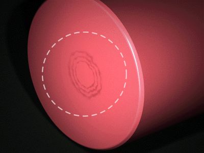
Ring around the gate
A ring-shaped pattern concentric with the gate, especially common with ABS-family resins.
Ring around the gate defect example
Causes and Solutions
Process Conditions
Cause
Excessive cooling at the gate or thin sections causes flow stagnation (from low molding temperature, slow injection speed, or low mold temperature). If the incoming molten resin is cooler than the mold or passes through a thin section, premature solidification reduces flow, typically occurring at the smaller-area gate section.
Solution
Raise molding temperature, increase injection speed (note: too fast can cause jetting), and raise mold temperature. (This defect typically occurs at gates with small cross-sections, so it should be distinguished from jetting/whitening at the gate.)
Mold
Cause
Gate size is too small.
Solution
Increase gate size.
Part Weight Variation
Inconsistent part weight (and dimensions) as production continues.
Causes and Solutions
Process Conditions
Cause
Screw damage.
Solution
Inspect the check ring and replace if needed.
Cause
Uneven metering / inconsistent injection stroke.
Solution
Set an appropriate back pressure, and ensure a sufficient screw cushion (melt cushion) remains during molding.
Cause
Malfunctioning temperature controls (cylinder heaters/sensors and mold temperature controller).
Solution
Inspect the injection molding machine. Uneven metering is closely tied to part weight and dimensional consistency, so when this issue occurs, check the screw check ring for damage first. Check ring wear is often too subtle to detect visually, so it's best to inspect it whenever metering becomes inconsistent, or replace it on a regular schedule. To check for check ring wear: as the screw rotates and advances during injection, weight should increase proportionally with any increase in shot size (stroke) — if the part weight doesn't increase to match the increased metered volume, the check ring may be worn.
Material
Cause
Inconsistent injection stroke.
Solution
If using regrind/scrap material, keep pellet size consistent, and dry the resin thoroughly.
Solve Injection Molding Defects with Creallo
Most of the defects covered here — short shots, flash, sink marks, weld lines, and more — can largely be prevented at the mold design and material selection stage, not just through process tuning. Considering moldability early in the design process significantly reduces defect rates and rework costs.
Creallo supports everything from prototyping to full-scale mass production. Simply upload your drawing to get a manufacturability review, real-time quote, and order placement — with experienced engineers reviewing molding conditions and mold design together to ensure consistent quality.
Start your injection molding project with Creallo now.